166 SBCSU - Station and S0 bus Configuration of SWU
The AMO SBCSU configures terminal devices (stations) at S0 bus connections, S0 interfaces, Up0/E interfaces, IP interface and on the ATM switch. A maximum of one voice terminal may be assigned to an S0 bus. A maximum of three terminals with three different station numbers can be set up per Up0/E access. Apart from configuring stations, the AMO SBCSU offers the options of displaying, regenerating and changing the associated data, as well as cancelling station assignments.
The AMO SBCSU assigns all station combinations which contain the following terminals. All other station combinations are assigned with the aid of the AMOs SCSU or SSCSU.
|
•
|
|
•
|
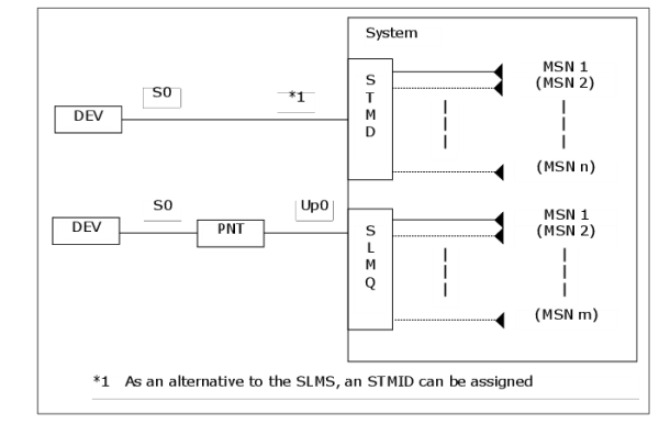
To assign additional station numbers, please refer to chap. “Multiple Subscriber Numbers (MSN) - MSN on the S0 bus”.
With an OPTISET connection to the SLMO, SLMQ-EXT or STMA-PSW a maximum of three terminals under a maximum of three different station numbers can be set up. Permitted terminals for this purpose are: CorNet-TS terminals (OPTISET, OPTIP500), analog terminals (ANADEV, ANAFAX, ANADTE) or terminals with an S0 interface (API, SET600, FAX, DTE).
Only one analog terminal (regardless of which type) can be set up on an OPTISET connection: either an analog non-voice terminal (i.e. ANAFAX or ANADTE) on the main station number or a general analog terminal (ANADEV) under a secondary station number.
A functional terminal of one type can be set up only once per OPTISET access. However, up to a maximum of two CorNet-TS and CorNet-T terminals of the same type can be installed. Functional terminals can also be reached via MSN station numbers (see also Chapter “Multiple Subscriber Numbers (MSN) - MSN for OPTISET configurations”).
A functional terminal of one type can be set up only once per OPTISET access. However, up to a maximum of two CorNet-TS and CorNet-T terminals of the same type can be installed. Functional terminals can also be reached via MSN station numbers (see also Chapter “Multiple Subscriber Numbers (MSN) - MSN for OPTISET configurations”).
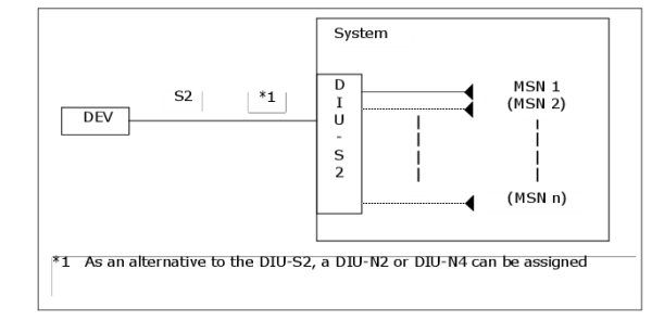
To assign additional station numbers, please refer to chap. “Multiple Subscriber Numbers (MSN) - MSN for functional point-to-point connections”.
Terminals OPTISET and OPTIP500 can also be installed as signed-off subscribers. These are not assigned a location. Locations entered for signed-off subscribers are ignored. Signed-off subscribers can sign on by means of a registration code number and PIN at any suitable terminal, or they can sign on via a suitable terminal at the appropriate location, or they can be signed on at a suitable location by means of AMO DSSU.