5.5.1. Feature Description 


This feature is used to automatically detect the topology of a OpenScape
4000 network and communicate the topology data to the higher-level tools
such as Remote Service Platform-Smart.
To this end, provided the feature has been activated, a so-called
"partner table" which can be queried with the AMO KNTOP is established
automatically in every OpenScape 4000 node. This table contains information
per B-channel group concerning the partner nodes (adjacent node = nearest
transit node) connected via this B-channel group in the circuit.
By querying all nodes, i.e. calling up the AMO KNTOP in all nodes,
the tool determines the topology of the entire network.
This feature always uses the physical node numbers / node access codes
(defined in the AMO ZAND), not the virtual ones,for example, configured
in the AMO KNDEF.
Automatic detection only functions in a homogenous OpenScape 4000/HiPath
4000 network. CorNet-NQ with Segmentation 8 must be configured as the
networking protocol. Components which convey the CorNet-NQ protocol transparently
are not detected (e.g. ATM networks, multiplexers, ViNet). However, the
OpenScape 4000 nodes networked via such installations do appear in the
topology. Remote IP access points are not detected. Only the OpenScape
4000 host system is detected, as only the host system is assigned a physical
node number.
In heterogeneous networks (e.g. with Hicom 300 nodes), you can use the AMO KNTOP to
perform
manual entries in the partner table which can no longer be overwritten by automatic
entries.
You also have the option of marking manual entries as over-writeable. These can then
be
replaced by automatic entries. The purpose of this is to configure Hicom 300 nodes
which you
know will be upgraded to OpenScape 4000 in future with this marker, thus avoiding
the need to
subsequently perform changes with the AMO KNTOP.
Figure 11. Example: Homogenous OpenScape 4000/HiPath 4000 network
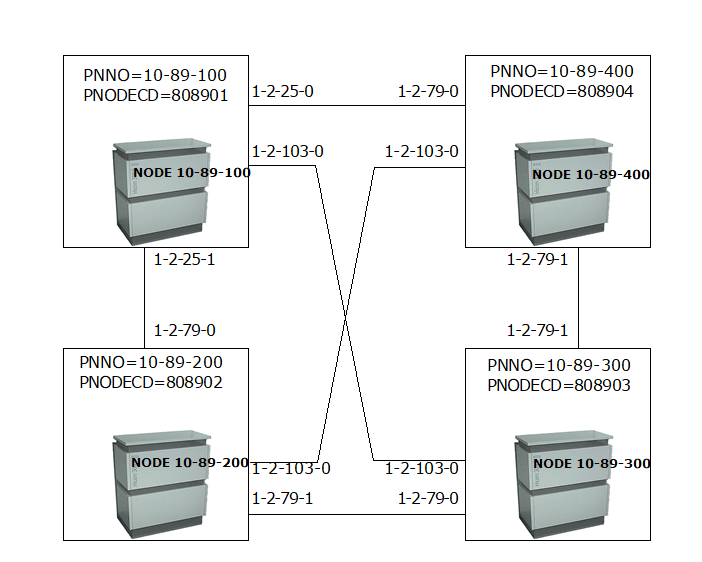
In Figure 11, Example: Homogenous
OpenScape 4000/HiPath 4000 network, the physical nodes are specified
with the AMO ZAND designations PNNO and PNODECD. The tie lines are designated
by specifying the port equipment number (PEN) in the corresponding partner
nodes. The tie trunk circuits can be S0 or S2 circuits (also ATM circuits);
CorNet-NQ with Segmentation 8 must be assigned to all circuits as the
networking protocol.
In nodes 10-89-100, the following information is stored in the partner
table:
- The line at the tie trunk circuit with PEN 1-2-25-0 leads to the physical node with the node number 10-89-400 and the node access code 808904 (partner node). In the partner node, this line is connected to PEN 1-2-79-0.
- The line at circuit 1-2-25-1 leads to partner node 10-89-4200 (node access code 808902). There, this line is connected to circuit 1-2-79-0.
- The line at circuit 1-2-103-0 leads to partner node 10-89-300 (node access code 808903). There, this line is connected to circuit 1-2-103-0.
In node 10-89-400, the following information is stored in the partner table:
- The line at circuit 1-2-79-0 leads to partner node 10-89-100 (node access code 808901). There, this line is connected to circuit 1-2-25-0.
- The line at circuit 1-2-79-1 leads to partner node 10-89-300 (node access code 808903). There, this line is connected to circuit 1-2-79-1.
- The line at circuit 1-2-103-0 leads to partner node 10-89-200 (node access code 808902). There, this line is connected to circuit 1-2-103-0.
The same principle applies to the entries in the partner tables of the remaining nodes.
The user tool (e.g. Remote Service Platform) can detect and graphically display the
connecting lines by assigning the nodes / PEN pairs of all partner tables. For example,
the
partner tables of 10-89-100 and 10-89-400 contain the matching pairs:
- 10-89-100: Circuit 1-2-025-1 leads to node 10-89-200, where the circuit is 1-2-079-0
- 10-89-100: Circuit 1-2-025-0 leads to node 10-89-400, where the circuit is 1-2-079-0
- 10-89-100: Circuit 1-2-103-0 leads to node 10-89-300, where the circuit is 1-2-103-0
This means that a connecting line exists between these points.