7.8.10.1. Internal Call Data Recording in the Network 


You can configure charges for internal traffic not only within a node,
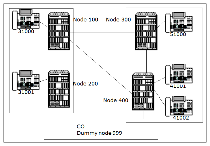
but also in a private network. The following example shows an entire
network, which consists of 2 sub-networks (shown inside the dashed lines)
for charging purposes. Internal charges are calculated inside these sub-networks.
Networking charges for outgoing calls are calculated between the sub-networks,
because, for example, the network connections (node 100 <-> node
400 and node 100 <-> node 300) are leased from a network operator.
Figure 89. Charges for internal traffic and outgoing networking
Scenario 1: Station 41001 calls station 41002. 41001 is in an ITR
group that is assigned the charge group INT01 (for example, EUR 0.30/MIN
during the day, EUR 0.20 at night). 41001 sees the in-progress charges
updated periodically on its display. After hanging up, the total charges
for the call are displayed after a set time.
Scenario 2: Station 41002 calls station 51000. The outgoing trunk
group is determined with LCR. Zone INT01 is again assigned to the LCR
routing element. The INTCHARG identification is also set so that external
charges are treated as internal ones. From the station's perspective,
scenario 2 is the same as scenario 1.
Scenario 3: Station 41001 calls 31000. Because 31000 is not in the
same sub-network and is reached via chargeable tie trunks, a networking
zone (such as TIE01) is assigned to the corresponding LCR routing element.
The charges differ from those in scenarios 1 and 2.
Scenario 4: Station 31000 dials a CO number. If, for example, the
tie trunk group nodes 100 - 200 and the first overflow trunk group nodes
100 - 400 are seized, a route node 100-300-400 is seized. No networking
charges should be calculated in transit node 300 and source node 100.
In this case, the corresponding route element in source node 100 is given
the attribute NOTRANS and the message so that no call data recording
is activated in transit node 300. Call data recording is always active
in trunk breakout node 400. In the example, trunk access is only allowed
for the LCR service VCE (voice + fax).
IMPORTANT:
All commands
that are shown in boldface are specifically for call data recording.
Configuration commands in node 100:
- Add a separate node number with:
CHA-ZAND:TYPE=ALLDATA,PNNO=100;
- If necessary, increase the buffer for cost calculation with:
ADD-DIMSU:TYPE=BASIC,COSTI=1000;
- Define amounts instead of units on the device with:
CHA-ZAND:TYPE=CCD,CDDISPEX=AMOUNT;
- Configure the charge display timer with:
CHA-CTIME:TYPESWU=CP1,DISPCH=25,CDRDISDE=10;
- Add the station numbers for closed numbering in the DPLN as follows:
ADD-WABE:CD=0,DPLN=0,DAR=CO;

ADD-WABE:CD=31000,DAR=STN;

ADD-WABE:CD=41001&41002,DAR=NETW,DESTNO=4;

ADD-WABE:CD=31001,DAR=NETW,DESTNO=2;

ADD-WABE:CD=51000,DAR=NETW,DESTNO=3;

ADD-WABE:CD=001&002&003, DAR=NETRTE;
- Assign the zone for ITR 0 internal traffic as follows:
ADD-VBZGR:GROUP=0,TYPE=CHRGINT,ITRGRB=0,
ZONE=INT01;
- Create the COS with the charge authorizations as follows:
CHA-COSSU:TYPE=COS,COS=2,AVCE=CDRINT&CDRSTN&CDRS,
AFAX=CDRINT&CDRSTN,ADTE=CDRINT&CDRSTN;
- Add the LCR routes as follows:
CHA-COSSU:TYPE=LCOSV,LCOSV=15,ALAUTH=1&2;
(for example, LCOS authorization PBX-NETWORK + CO)

CHANGE-COSSU:TYPE=LCOSD,LCOSD=5,ALAUTH=1;
(for example, data only in PBX network)

ADD-BUEND:TGRP=20,NAME=K100TO200,NO=30;

ADD-BUEND:TGRP=30,NAME=K100TO300,NO=30;

ADD-BUEND:TGRP=40,NAME=K100TO400,NO=30;

ADD-TDCSU:OPT=NEW,COTNO=11,LCOSV=1,LCOSD=1,
DEV=S2CONN,PROTVAR=ECMA1,TGRP=20,BCGR=2;

ADD-TDCSU:OPT=NEW,COTNO=11,LCOSV=1,LCOSD=1,
DEV=S2CONN,PROTVAR=ECMA1,TGRP=30,BCGR=2;

ADD-TDCSU:OPT=NEW,COTNO=11,LCOSV=1,LCOSD=1,
DEV=S2CONN,PROTVAR=ECMA1,TGRP=40,BCGR=2;

ADD-RICHT:MODE=CD,CD=001,LRTE=55,CPS=0,
SVC=ALL,TGRP1=20,DESTNO=2,DNNO=200;

ADD-RICHT:MODE=CD,CD=002,LRTE=66,CPS=0,
SVC=ALL,TGRP1=30&40,DESTNO=3,DNNO=300;

ADD-RICHT:MODE=CD,CD=003,LRTE=77,CPS=0,
SVC=ALL,TGRP1=30&40,DESTNO=4,DNNO=400;

ADD-RICHT:MODE=LRTENEW,LRTE=88,LSVC=VCE,
TGRP=20&30&40,DNNO=999;

ADD-KNDEF:NNO=<level2>-<level1>-<level0>,
ISDNCC=49,ISDNAC=89,ISDNLC=722;
- Configure the outdial rule for the CO (open numbering) as follows:
ADD-LODR:ODR=1,CMD=ECHO,FIELD=1;
(send the dialed 0)

ADD-LODR:ODR=1,CMD=ECHO,FIELD=2;
(send the rest of the station number)

ADD-LODR:ODR=1,CMD=END;
- Assign the outdial rule for networking (closed numbering) as follows:
ADD-LODR:ODR=2,CMD=ECHO,FIELD=1;
(send the entire station number)

ADD-LODR:ODR=2,CMD=END;
- Define the LCR elements with trunk group seizure order as follows:
ADD-LDAT:LROUTE=55,LSVC=ALL,LVAL=1,
TGRP=20,LAUTH=1,ODR=2;

ADD-LDAT:LROUTE=66,LSVC=ALL,LVAL=1,TGRP=30,
LAUTH=1,ODR=2;

ADD-LDAT:LROUTE=66,LSVC=ALL,LVAL=2,TGRP=40,
LAUTH=1,ODR=2;

ADD-LDAT:LROUTE=77,LSVC=ALL,LVAL=1,TGRP=40,
LAUTH=1,ODR=2;

ADD-LDAT:LROUTE=77,LSVC=ALL,LVAL=2,TGRP=30,
LAUTH=1,ODR=2;

ADD-LDAT:LROUTE=88,LSVC=VCE,LVAL=1,TGRP=20,
LAUTH=2,ODR=1;

ADD-LDAT:LROUTE=88,LSVC=VCE,LVAL=2,TGRP=40,
LAUTH=2,ODR=1;

ADD-LDAT:LROUTE=88,LSVC=VCE,LVAL=3,TGRP=30,
LAUTH=2,ODR=1;
- Add the dialing plan for the CO:
ADD-LDPLN:LDP=0-Z,LROUTE=88,LAUTH=2;
- Give the LCR elements charge attributes as follows:
CHA-LDAT:LROUTE=55,LSVC=ALL,LRTEL=1,
CARRIER=1,ZONE=INTERN01,LATTR=WCHREG&INTCHARG;

CHA-LDAT:LROUTE=66&77,LSVC=ALL,LRTEL=1&2,
CARRIER=1,ZONE=TIE01,LATTR=WCHREG;

CHA-LDAT:LROUTE=88,LSVC=VCE,LRTEL=1&2&3,
LATTR=WCHREG&NOTRANS;
- Parameterize the stations as follows:
CHA-SBCSU:STNO=31000,COS1=2,COS2=2,LCOSV1=15,
LCOSV2=15,LCOSD1=5,LCOSD2=5,ITR=0;
- Activate the features (charges for the trunk, tie, and internal) centrally as follows:
CHANGE-FEASU:TYPE=A,CM=CDROGTR&DISCHTR&
CDROGNW&DISCHNW&CDRINH&DISCHINH;
Configuration commands in node 400:
- Add a separate node number as follows:
CHA-ZAND:TYPE=ALLDATA,PNNO=400;
- If necessary, increase the buffer for cost calculation with:
ADD-DIMSU:TYPE=BASIC,COSTI=1000;
- Amounts instead of units at the device with:
CHA-ZAND:TYPE=CCD,CDDISPEX=AMOUNT;
- Configure the charge display timer as follows:
CHA-CTIME:TYPESWU=CP1,DISPCH=25,CDRDISDE=10;
- Add the station numbers in WABE as follows:
ADD-WABE:CD=0,DPLN=0,DAR=CO;

ADD-WABE:CD=41001&41002,DAR=STN;

ADD-WABE:CD=31000,DAR=NETW,DESTNO=1;

ADD-WABE:CD=31001,DAR=NETW,DESTNO=2;

ADD-WABE:CD=51000,DAR=NETW,DESTNO=3;

ADD-WABE:CD=001&002&003, DAR=NETRTE;
- Assign the zone for internal traffic in ITR 0 as follows:
ADD-VBZGR:GROUP=0,TYPE=CHRGINT,ITRGRB=0,
ZONE=INT01;
- Create the COS with the charge authorizations as follows:
CHA-COSSU:TYPE=COS,COS=2,AVCE=CDRINT&CDRSTN&CDRS,
AFAX=CDRINT&CDRSTN,ADTE=CDRINT&CDRSTN;
- Configure the COT with DPRE (for trunk circuits) as follows:
CHA-COT:COTNO=12,COTTYPE=COTADD,PAR=DPRE&LWNC&NLCR;
- Add the LCR routes as follows:
CHA-COSSU:TYPE=LCOSV,LCOSV=15,ALAUTH=1&2;
(for example, LCOS authorization PBX-Network + CO)

CHANGE-COSSU:TYPE=LCOSD,LCOSD=5,ALAUTH=1;
(for example, data only in PBX network)

ADD-BUEND:TGRP=11,NAME=K400TO100,NO=30;

ADD-BUEND:TGRP=31,NAME=K400TO300,NO=30;

ADD-BUEND:TGRP=44,NAME=K400TOAMT,NO=30;

ADD-TDCSU:OPT=NEW,COTNO=11,LCOSV=1,LCOSD=1,
DEV=S2CONN,PROTVAR=ECMA1,TGRP=11,BCGR=2;

ADD-TDCSU:OPT=NEW,COTNO=11,LCOSV=1,LCOSD=1,
DEV=S2CONN,PROTVAR=ECMA1,TGRP=31,BCGR=2;

ADD-TDCSU:OPT=NEW,COTNO=12,LCOSV=1,LCOSD=1,
GER=S2COD,PROTVAR=ETSI,TGRP=44,BCGR=2,NNO=999,
ISDNIP=00,ISDNNP=0;

ADD-RICHT:MODE=CD,CD=001,LRTE=55,CPS=0,
SVC=ALL,TGRP1=11&31,DESTNO=1,DNNO=100;

ADD-RICHT:MODE=CD,CD=002,LRTE=66,CPS=0,SVC=ALL,
TGRP1=11&31,DESTNO=2,DNNO=200;

ADD-RICHT:MODE=CD,CD=003,LRTE=77,CPS=0,
SVC=ALL,TGRP1=11&31,DESTNO=3,DNNO=300;

ADD-RICHT:MODE=LRTENEW,LRTE=88,LSVC=VCE,
TGRP=11&31&44,DNNO=999;

ADD-KNDEF:NNO=<level2>-<level1>-<level0>,
ISDNCC=49,ISDNAC=89,ISDNLC=722;
- Configure the outdial rule for the CO (via a tie trunk) as follows:
ADD-LODR:ODR=1,CMD=ECHO,FIELD=1;
(send the dialed 0)

ADD-LODR:ODR=1,CMD=ECHO,FIELD=2;
(send the rest of the station number)

ADD-LODR:ODR=1,CMD=END;
- Assign the outdial rule for networking (closed numbering) as follows:
ADD-LODR:ODR=2,CMD=ECHO,FIELD=1;
(send the entire station number)

ADD-LODR:ODR=2,CMD=END;
- Configure the outdial rule for the CO (direct connection) as follows:
ADD-LODR:ODR=3,CMD=ECHO,FIELD=2;
(send the station number without "0")

ADD-LODR:ODR=3,CMD=END;
- Define the LCR elements with trunk group seizure order as follows:
ADD-LDAT:LROUTE=55,LSVC=ALL,LVAL=1,TGRP=11,
LAUTH=1,ODR=2;

ADD-LDAT:LROUTE=55,LSVC=ALL,LVAL=1,TGRP=31,
LAUTH=1,ODR=2;

ADD-LDAT:LROUTE=66,LSVC=ALL,LVAL=1,TGRP=11,
LAUTH=1,ODR=2;

ADD-LDAT:LROUTE=66,LSVC=ALL,LVAL=2,TGRP=31,
LAUTH=1,ODR=2;

ADD-LDAT:LROUTE=77,LSVC=ALL,LVAL=1,TGRP=31,
LAUTH=1,ODR=2;

ADD-LDAT:LROUTE=77,LSVC=ALL,LVAL=2,TGRP=11,
LAUTH=1,ODR=2;

ADD-LDAT:LROUTE=88,LSVC=VCE,LVAL=1,TGRP=44,
LAUTH=2,ODR=3;

ADD-LDAT:LROUTE=88,LSVC=VCE,LVAL=2,TGRP=11,
LAUTH=2,ODR=1;

ADD-LDAT:LROUTE=88,LSVC=VCE,LVAL=3,TGRP=31,
LAUTH=2,ODR=1;
- Add the dialing plan for the CO:
ADD-LDPLN:LDP=0-Z,LROUTE=88,LAUTH=2;
- Give the LCR elements charge attributes as follows:
CHA-LDAT:LROUTE=77,LSVC=ALL,LRTEL=1,CARRIER=1,
ZONE=INTERN01,LATTR=WCHREG&INTCHARG;

CHA-LDAT:LROUTE=77,LSVC=ALL,LRTEL=2,CARRIER=1,
ZONE=TIE02,LATTR=WCHREG&NOTRANS;
(transit node 100 without charge)

CHA-LDAT:LROUTE=55&66,LSVC=ALL,LRTEL=1&2,CARRIER=1
,ZONE=TIE01,LATTR=WCHREG;

CHA-LDAT:LROUTE=88,LSVC=VCE,LRTEL=1,LATTR=WCHREG;

CHA-LDAT:LROUTE=88,LSVC=VCE,LRTEL=2&3,
LATTR=WCHREGT&NOTRANS;
- Parametrize the stations as follows:
CHA-SBCSU:STNO=41001&&41002,COS1=2,COS2=2,
LCOSV1=15,LCOSV2=15,LCOSD1=5,LCOSD2=5,ITR=0;
- Proceed as follows to activate the feature centrally:
CHA-FEASU: TYPE=A,CM=CDROGTR&DISCHTR&
CDROGNW&DISCHNW&CDRINT&DISCHINH;
Configuration commands in nodes 200 and 300:
Configure node 200 (with trunk connection) in the same way as node
100, in principle, like nodes 400 and 300.