10.41.5.3. Master/Slave Configuration Downstream from Up0 Extender
(Phone Adapter) 


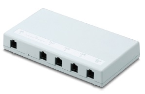
Figure 110. Phone adapter (Up0 extender)
Possible use
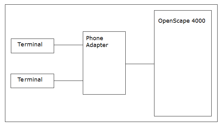
The following terminals can be connected to the phone adapter:
- Up0 system telephone:
- OpenStage 20 T
- OpenStage 40 T
- OpenStage 60 T and 80 T (require their own power supply unit)
- optiPoint 500 (must be connected to Up0 Slave output socket)
- Analog device:
- Phone with MFV tone dialing (e. g. Euroset 5020 or a cordless phone such as Gigaset A160),
- a Group 3 fax or
- a modem.
IMPORTANT:
Analog telephones at the phone adapter act as DSS1 phones. Therefore the same call processing features available to S0/S2 terminals with the E-DSS1 protocol are also available to the analog terminals at the telephone adapter. This means that some of the normally available ANATE features are not supported. For example: PIN-specific features, such as class-of-service changeover, follow me/FWD transfer, Autoset relocate, Night stationThe Phone Adapter can be used in the following configurations only: - One Up0 system telephone (Up0 Master)
- Two Up0 system telephones (Up0 Master, Up0 Slave)
- One Up0 system telephone and one analog terminal (Up0 Master, a/b)
IMPORTANT:
It is not possible to operate two Up0 system telephones
and one analog device.
Installation
Ports on the Phone adapter
There are five sockets (from right to left):
- Power
- Up0-IN (from the OpenScape 4000)
- Up0-Out1 (to the master phone) = Up0 Master output socket
- Up0-Out2 (to the slave phone) = Up0 slave output socket
- a/b = analog output socket
A small slide switch is located between the Up0-Out2 and the a/b. When the slide switch
is
moved, the output closest to it is enabled:
- if the switch is moved to the left towards the a/b socket -> the a/b (analog) output is enabled, you can connect an analog device
- If the switch is moved to the right: the Up0 slave is enabled, you can connect a further Up0 phone
The switch is read during power-up, and then enables the appropriate output.
Reconfiguration during live operation is therefore not possible.
You must connect an OpenStage phone to the "Up0 Master output socket" in order to
be able
to operate devices on the "Up0 Slave" and "Analog" output sockets..
Example
Up0 master:
ADD-SBCSU:STNO=3100,OPT=OPTI,CONN=DIR,PEN=number,
DVCFIG=OPTISET&VIRTDTE,COS1=number,
COS2=number,LCOSV1=number,LCOSV2=number,LCOSD1=number,
LCOSD2=number,DPROT=SBDSS1,DOPTIDX=1;
Up0 slave:
ADD-SBCSU:STNO=3101,OPT=OPTIEXP,MAINO=3100,
DVCFIG=OPTISET&VIRTDTE,DPROT=SBDSS1,
DOPTIDX=1;
The terminal must now still be activated:
RESTART-DSSU:TYPE=STNO,STNO=3100&3101;
or
Analog device:
The analog device can be configured with the same call number as ANAFAX:
ADD-SBCSU:STNO=3100,OPT=OPTI,CONN=DIR,PEN=number,
DVCFIG=OPTISET&VIRTDEE&ANAFAX,COS1=number,
COS2=number,LCOSV1=number,LCOSV2=number,LCOSD1=number,
LCOSD2=number,DPROT=SBDSS1,DOPTIDX=1;
or as an analog device with another call number:
Up0 master:
ADD-SBCSU:STNO=3100,OPT=OPTI,CONN=DIR,PEN=number,
DVCFIG=OPTISET&VIRTDEE,COS1=number,COS2=number,
LCOSV1=number,LCOSV2=number,LCOSD1=number,
LCOSD2=number,DPROT=SBDSS1,DOPTIDX=1;
Up0 slave:
ADD-SBCSU:STNO=3101,OPT=OPTIEXP,MAINO=3100,
DVCFIG=ANADEV;
For further details on the Phone adapter please refer
to the installation guide.