2.1.5.4. Clock Drift with Static Jitter Buffer 


With digital voice transmission in ISDN, all transmission devices
operate synchronously. In other words, the volume of voice data per time
unit is absolutely the same for the sender and the receiver. For this
purpose, transmission devices are synchronized to a common clock pulse
(clock signal).
With digital voice transmission over IP, the transmission devices
operate asynchronously. Exception: IPDA access point with digital trunk
connection can synchronize with the clock signal. This asynchronicity
means that more or fewer packets are created per second at the transmitting
end than are expected at the receiving end. This discrepancy is called
clock drift.
If more packets are created at the transmitting end than are expected
by the receiver, more packets enter the jitter buffer than intended.
This leads to a constant increase in the measured average delay. If this
reaches the configured maximum delay value, the jitter buffer adjusts
itself. It skips surplus packets until the measured average delay reverts
to the set value for average delay. The entire procedure is then restarted.
The following figure illustrates the procedure:
Figure 7. Clock drift in static jitter buffer [transmission quicker than receipt]
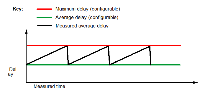
If, for example, the average delay is set to 40 ms and the maximum
delay to 80 ms, this means that the measured overall delay will increase
at intervals by 40 ms from the start value. The length of the interval
will be determined by the clock pulse difference of the clock pulse generators
in the central system (for all HG 3500 systems) or on the HG 3575 boards
as well as on the configuration data (difference between the maximum
and the average value). In the sample configuration (40 ms delay hub)
the interval is between approximately 30 and 120 minutes long.
If fewer packets are generated at the transmitting end than are expected
by the receiver, more packets enter the jitter buffer than intended.
This leads to a constant decrease in the measured average delay. If,
as a result, the number of packets located in the jitter buffer is reduced
to zero, the jitter buffer adjusts itself and resets the measured average
delay to the set value for average delay by inserting packets. The entire
procedure is then restarted. The following figure illustrates the procedure:
Figure 8. Clock drift in static jitter buffer [transmission slower than receipt]
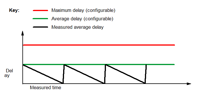
If, for example, the average delay has been set to 40 ms, this means
that the measured overall delay is reduced at intervals from the start
value by 40 ms. The length of the interval depends on the clock pulse
difference of the clock pulse generators in the central system (for all
HG 3500 systems) or on the HG 3575 boards as well as on the configuration
data (difference between the maximum and the average values). In the
sample configuration (40 ms delay hub) the interval is between approximately
30 and 120 minutes long.
The variation in the overall delay caused by clock drift can be completely
avoided by synchronizing the components involved with a common clock
pulse.