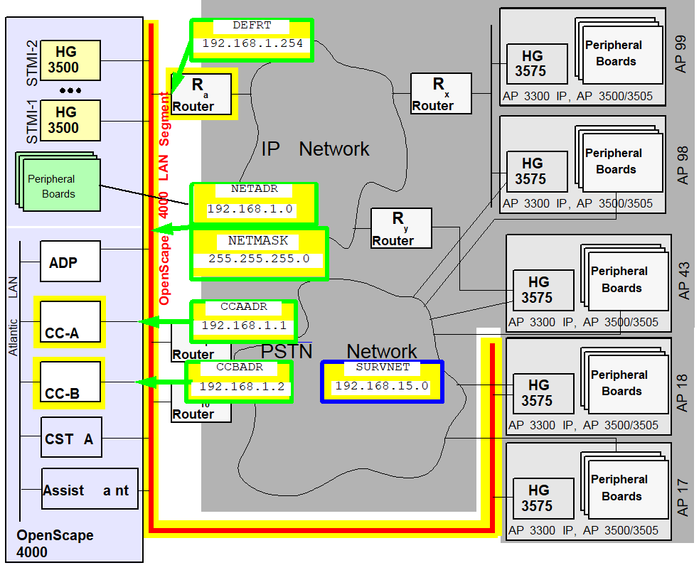
10.2.1. OpenScape 4000 LAN Segment 


The OpenScape 4000 LAN segment is that part of the customer network in which the IP
components of
the central system and direct link (i.e. not via router) access points are installed.
Figure 177. OpenScape 4000 LAN segment
ADD-SIPCO: |
NETADDR=192.168.1.0, |
NETMASK=255.255.255.0, |
|
IPMODE=IPV4,
|
DEFRT=192.168.1.254, |
|
CCAADDR=192.168.1.1, |
CCBADDR=192.168.1.2, |
|
SURVNET=192.168.15.0; |
At maximum capacity, a configuration requires a considerable number
of IP addresses in this network, namely.
|
3
|
|
1
|
|
1
|
|
Up to 83
|
|
Up to 83
|
|
Up to 10
|
Therefore, it is advisable to configure a dedicated LAN segment for
the central part of a large OpenScape 4000 installation and not permit
any more nodes within that segment (particularly file servers, etc.)
For demo installations in which the OpenScape 4000 LAN segment remains
isolated, IP addresses from the private address range pursuant to RFC
1597 can be used. These do not require international coordination. For
example, the range from 192.168.1.1 to 192.168.1.255 with netmask 255.255.255.0
can be recommended as the Class C address range.
Generation
Addresses (LSNET)
The first step in configuring IP distributed architecture involves
the configuration of the OpenScape 4000 LAN segment.
Configuration:
|
|
Configuration Management > System Data > IPDA > IPDA System Data
Click Search, enter the required IP addresses and Save.
|
|
|
ADD-SIPCO:NETADDR=192.168.1.0,NETMASK=255.255.255.0,
                                 DEFRT=192.168.1.254,IPMODE=IPV4,CCAADDR=192.168.1.1,
CCBADDR=192.168.1.2,SURVNET=192.168.15.0; |
IMPORTANT:
Although the CCA/CCB address already had to be
entered when the configuration was performed with the LAN Wizard, it
has to be configured again here with AMO SIPCO.
If an isolated configuration is to be set up, the default router must
be configured with the zero address
0.0.0.0. In this
case, only “direct link“ access points can be configured (see Section 2.2.2,
“Configuring a “Direct Link“ Access Point”).
In Figure 12 “OpenScape 4000 LAN segment”,
Router Ra is the default router. If there is no second processor, the CCBADDR parameter need
not be specified.
The SURVNET parameter can be dispensed with if signaling survivability
is not required. If, however, the customer has purchased signaling survivability,
i.e. if the corresponding license counter is greater than zero, then
a survivability network address (see section Signaling Survivability)
must be specified. This can also be achieved with a dummy entry (zero
address
0.0.0.0), though the signaling survivability
function is not available in this case.The licenses for signaling survivability can be queried as follows:
|
|
Configuration Management > HiPath Inventory
Management
> HIM System Data > Feature > Marketing
Units
Click Search > Sales Features tab >
Signaling Survivability entry
|
|
|
DISP-CODEW; “SIGNALING SURVIVABILITY“
entry |
The values specified with ADD-SIPCO are immediately valid.
IMPORTANT:
Prior to
ADD-SIPCO, use ping
to check that the IP addresses given to you by the administrator are
reachable. CCAADDR and CCBADDR must not be reachable as
this would indicate that the corresponding address had already been assigned. DEFRT
must be reachable (if not 0.0.0.0).IMPORTANT:
Following
ADD-SIPCO the
active processor must be reachable in its network segment. The standby
processor in duplex systems does not respond (as long as it is in standby
mode). Since routes have not yet been configured, the active processor
cannot answer ping requests from other network segments!Change:
All parameters configured here can be changed later.
|
|
Configuration Management > System Data
> IPDA > IPDA System Data
Click Search, change
the addresses and Save.
|
|
|
CHANGE-SIPCO:TYPE=LSNET; |
The parameters are not immediately effective after the CHANGE, but
only once the system has been restarted. The database must be backed
up beforehand to disk.
|
|
The restart can only be performed in expert
mode.
Expert Mode > Expert Access > Open ...<IP>
with AMO (see AMO command)
|
|
|
EXEC-UPDAT:BP,ALL; EXEC-REST:SYSTEM,RESTART; |
IMPORTANT:
Changing the IP address has multifarious effects
on a running system. If changes are necessary, a strict change sequence
must be complied with, or else the access points will be irrevocably
disconnected. In this context, see Section 2.14,
“IP Address Changes”.
Delete:
If, for instance, IPDA is to be completely removed from the system
after a test, all access points and HG 3500, as well as the SIPCO configuration,
also have to be deleted after the uninstall routine is completed. The
links/LAN modules for the OpenScape 4000 LAN segment can then also be
removed. You must restart the system.
|
|
Deletion can only be performed in expert mode.
Expert
Mode > Expert Access > Open ...<IP> with AMO (see AMO
command)
|
|
|
DELETE-SIPCO;EXEC-UPDAT:BP,ALL; EXEC-REST:SYSTEM,RESTART; |
List of AMO parameters for Add / Change:
Table 30. AMO SIPCO parameters in ADD branch or for CHANGE under TYPE=LSNET
|
AMO
|
Parameter
|
Sprache/ Language
|
Beschreibung/ Description
|
|
SIPCO
|
NETADR
|
d
|
Netzadresse des OpenScape 4000 LAN Segments
gilt
für CC-A, CC-B, alle HG 3500 (STMI2/4/STMIX/STMIY), Default-Router, Survivability-Router
und direkt angeschlossene Access Points
|
|
NETADDR
|
e
|
Network Address of the OpenScape 4000 LAN Segment
valid
for CC-A, CC-B, every HG 3500 (STMI2/4/STMIX/STMIY), default router, survivability
router and directly linked Access Points
|
|
|
NETMASK
|
d
|
Netzmaske des OpenScape 4000 LAN Segments
gültig
wie NETADR
|
|
|
NETMASK
|
e
|
Netmask of the OpenScape 4000 LAN Segment
valid
like NETADDR
|
|
|
DEFRT
|
d
|
Default-Router im OpenScape 4000 LAN Segment
über
diesen Router sollen alle nicht direkt im OpenScape 4000 LAN Segment
angeschlossenen Access Points von den HG 3500 Baugruppen erreicht werden.
Angegeben wird die IP-Adresse der Routers im OpenScape 4000 LAN Segment.
Falls
kein Default-Router benutzt werden soll, z. B. für isolierte Demo-Installationen
mit “direct link“ APs, muss die Adresse 0.0.0.0 angegeben werden.
|
|
|
DEFRT
|
e
|
Default Router in the OpenScape 4000 LAN Segment
via
this router all Access Points that are not directly linked to the OpenScape
4000 LAN Segment shall be reached by all HG 3500 boards.. The IP address
of this router in the OpenScape 4000 LAN Segment is to be given.
If
no default router shall be used, e.g. for stand-alone demo installations
with “direct link“ APs, give the address 0.0.0.0.
|
|
|
IPMODE
|
d
|
IP Mode. Muss für IPDA IPV4 sein.
|
|
|
IPMODE
|
e
|
IP mode. Must be set to IPV4 for IPDA.
|
|
|
CCAADR
|
d
|
IP-Adresse des CC-A Prozessors im OpenScape
4000 LAN Segment
|
|
|
CCAADDR
|
e
|
IP address of the CC-A Prozessor in the OpenScape
4000 LAN Segment
|
|
|
CCBADR
|
d
|
IP-Adresse des CC-B Prozessors im OpenScape
4000 LAN Segment
Nicht angeben, wenn kein CC-B im System
|
|
|
CCBADDR
|
e
|
IP address of the CC-B Prozessor in the OpenScape
4000 LAN Segment
Omit, if no CC-B in the system
|
|
|
SURVNET
|
d
|
Netzadresse des Survivability Netzes
Die
Netzmaske für das Survivability Netz ist mit 255.255.255.0 ebenso fest
vorgegeben wie die Adressierung der einzelnen Knoten. Die Survivability-Router
1..10 haben die Adressen 1..10, die Access Points 17..99 die Adressen
17..99 im letzten Byte. Die vorgegebene Netzmaske schränkt die Klasse
(A,B oder C) der Netzadresse nicht ein. Das Survivability Netz kann ein
Subnetz eines Klasse A Netzes mit Netzmaske 255.255.255.0 sein.
|
|
|
SURVNET
|
e
|
Network Address of the Survivability Network
The
netmask for the Survivability Network is fixed to 255.255.255.0 as well
as the individual node adresses. The survivability routers 1..10 are
addressed 1..10, Access Points 17..99 have address 17..99 in the last
byte. The given netmask does not limitate the class (A,B or C) of the
network address. The Survivability Network can be a subnet of a class
A network with netmask 255.255.255.0.
|
Quality of Service Parameters (DIFFSERV)
The following parameters can be set:
- For QoS support on Layer 2 to IEEE 802.1 q/q [
VLAN, VLANID]- For QoS support on Layer 3 to IETF RFC 2474 (DiffServ) [
TOSPL,
                              TOSSIGNL
] - the lowest port used for payload connections (UDP/RTP+RTCP) [
UDPPORT]
The Ethernet interface setting must be identical for all connected interface partners (CC-A and CC-B or LAN switches, routers).IMPORTANT:
The setting of a fixed interface partner leads to problems with the “Autonegotiate“ setting of the other partner. Caution: Incorrect settings cannot normally be detected by the system and therefore go unreported. If one device is operating in full duplex and the other in half duplex mode, this is not immediately noticeable. Where there is a high payload, the device set to half duplex will report a higher number of late collisions and the packet delay will increase sharply. If the LAN ports with which CC-A and CC-B are connected do not support autonegotiation, or if autonegotiation does not function reliably, the Ethernet interfaces of the central processors can be set to fixed values.VLAN tagging should only be activated when all routers in the network segment of the access point support VLAN tagging. The same applies for the DiffServ CodePoints. If the routers do not support DiffServ, the standard TOS values must be configured without DiffServ. If DiffServ is supported, but not the CodePoints, the values specified by the network carrier must be configured.Given that some network component vendors only support prioritization with VLAN ID > 0 pursuant to IEEE 802.1 p/q, the VLAN ID can also be set. The HG 3575 module generally sets the priority bits when the VLAN option is activated. For values, see Table 3 “TOS values” in document “Gateways HG 3500 and HG 3575”. According to the standard, the VLAN ID must then be set to zero, which also happens for the default setting.The parameters for configuring the TOS bytes for the various traffic types are provisioned with the DiffServ CodePoints pursuant to the company’s QoS Recommendation. VLAN tagging pursuant to IEEE 802.1 p/q is deactivated (VLAN=NO).If VLAN tagging pursuant to IEEE 802.1 p/q is supported in the OpenScape 4000 LAN segment, it can be activated as follows: Configuration Management > System Data > IPDA > IPDA System DataClick Search, activate the VLAN Tagging checkbox under Type of Service on the System Data tab, then Save.
CHANGE-SIPCO:TYPE=DIFFSERV,VLAN=YES;If DiffServ is not supported, the TOS bytes must be configured with content pursuant to RFC 791 (see Table 3 “TOS values” in document “Gateways HG 3500 and HG 3575”).Configuration Management > System Data > IPDA > IPDA System DataClick Search, enter the TOS values under Type of Service on the System Data tab, then Save.CHANGE-SIPCO:TYPE=DIFFSERV,TOSPL=16,TOSSIGNL=20;If either the VLAN or VLANID parameter has been changed, an update must be performed on the hard disk and then the system must be restarted.Configuration Management > Network > SystemClick Save on the Action pull-down menu.The restart can only be performed in expert mode.Expert Mode > Expert Access > Open ...<IP> with AMO (see AMO command)EXEC-UPDAT:BP,ALL; EXEC-REST:SYSTEM,RESTART; - For QoS support on Layer 3 to IETF RFC 2474 (DiffServ) [
Note:
VLAN tagging changes the packet header. Many L2 switches or routers
understand either packets with or without tagging. In other words,
- the relevant switches/routers also have to be adjusted.
- while the settings do not correspond, it is possible that packets
will not be transmitted.
- the conversion of the HG 3500 system interrupts payload connections
- the conversion of the OpenScape 4000 CCs interrupts the contact to all access points
A change of TOSPL is directly loaded on all HG 3500s and becomes effective immediately, without the operation of the modules having to be interrupted.The parameter TOSSIGNL does not become effective until the connection for which the TOS value is set has been cleared down and then set up again.The disconnection and re-establishment of the links between the OpenScape 4000 central system and access point can be realized through - a soft restart on the OpenScape 4000 system, which then affects all subscribers
|
|
The soft restart can only be performed in expert
mode.
Expert Mode > Expert Access > Open ...<IP>
with AMO (see AMO command)
|
|
|
|
- through DEACTIVATE-USSU and ACTIVATE-USSU for every individual access point, which then only affects the respective subscribers.
|
|
Configuration Management > System Data
> IPDA > IPDA Access Point
Click SEARCH and select
the access point.
Click Deactivate on the Action pull-down
menu.
Once the system has confirmed deactivation of the AP, reactivate
it with Activate.
|
|
|
|
The TOS bytes at the access points are configured specifically for
every access point.
If you want to locate the payload connections in a customer network
in a specific port range for reasons of port-based prioritization, for
example, then this can be set as follows:
|
|
Configuration Management > System Data
> IPDA > IPDA System Data
Click Search, enter
the base address of the UDP port under Type of Service on the
System Data tab, then Save.
|
|
|
|
Table 31. AMO SIPCO parameters in CHANGE branch under TYPE=DIFFSERV
|
AMO
|
Parameter
|
Sprache/ Language
|
Beschreibung/ Description
|
|
SIPCO
|
TOSPL
|
d
|
TOS-Byte für die VoIP Payload-Verbindungen
zwischen OpenScape 4000 und Access Point.
Gültig für Pakete
von beliebigen HG 3500 in Richtung Access Point.
|
|
TOSPL
|
e
|
TOS Byte for the VoIP payload connections between
OpenScape 4000 and Access Point.
Valid for packets from any HG
3500 towards Access Point.
|
|
|
TOSSIGNL
|
d
|
TOS-Byte für die Signalisierungsverbindungen
zwischen OpenScape 4000 und Access Point. (auch für Supervisory und
RTO)
Gültig für Pakete vom CC-A, CC-B in Richtung Access
Point.
|
|
|
TOSSIGNL
|
e
|
TOS Byte for the Signaling connections between
OpenScape 4000 and Access Point. (also for Supervisory and RTO)
Valid
for packets from CC-A, CC-B towards Access Point.
|
|
|
VLAN
|
d
|
Schaltet VLAN-Tagging nach IEE 802.1p/q ein
(JA) bzw. aus (NEIN).
Gültig für VoIP Payload-Verbindungen von
beliebigen HG 3500 in Richtung Access Point.
Gültig für Pakete
vom CC-A, CC-B in Richtung Access Point.
|
|
|
VLAN
|
e
|
Switches VLAN Tagging according to IEEE 802.1p/q
on (YES) or off (NO).
Valid for VoIP payload connections from any
HG 3500 towards Access Point.
Valid for packets from CC-A, CC-B
towards Access Point.
|
|
|
VLANID
|
d
|
VLAN-ID Wert für alle HG 3500 sowie CC-A und
CC-B
Nur von Bedeutung, wenn VLAN=JA.
12 Bit Wert, der gemäß
IEEE 802.1 p/q Standard auf Null gesetzt sein muss, wenn Priorisierung
verwendet wird (VLAN=JA).
Von dieser Standardeinstellung darf nur
abgewichen werden, wenn Netzwerkkomponenten bestimmter Hersteller erzwingen,
dass bei Nutzung der Priorisierung eine VLAN-ID > 0 zu verwenden ist.
|
|
|
VLANID
|
e
|
VLAN-ID value for all HG 3500, CC-A and CC-B
Only
relevant if VLAN=YES.
12 Bit value that, according to IEEE
802.1 p/q, has to be set to zero when prioritization is used (VLAN=YES).
This
standard setting may only be changed, if network components of certain
vendors enforce the usage of VLAN-ID > 0 while using prioritization.
|
|
|
UDPPORT
|
d
|
Einstellung des Basis-Ports (niedrigste Portnummer)
für Payloadverbindungen im IPDA-System
Für jede Payload-Verbindung
werden an den beteiligten Gateways HG 3500 bzw. HG 3575 ein UDP Port
für RTP und ein weiterer für RTCP benötigt. Die Portnummern werden
in einem Bereich von [UDPPORT .. UDPPORT+247] vergeben.
RTP belegt
dabei immer eine gerade Nummer, RTCP die nächst höhere ungerade.
Wertebereich:
[4352 .. 65038], nur gerade Zahlen erlaubt.
|
|
|
UDPPORT
|
e
|
Setting of the Base Port (lowest port number)
for Payload Connections in the IPDA System
For every payload connection
one UDP port is required for RTP and another for RTCP. The port numbers
are assigned in a range of [UDPPORT .. UDPPORT+247].
RTP always
uses an even number, RTCP the next higher odd one.
Value range:
[4352 .. 65038], only even numbers allowed.
|
Additional parameters
With ADD-SIPCO, additional system parameters are also set to default
values which can be changed by means of CHANGE-SIPCO. These parameters
are broken down into 2 groups.
System timing (TIMING)
Under TYPE=TIMING, central values of the system timing can be set
for the monitoring of IP links. If the values set here are exceeded,
the system switches the communication between OpenScape 4000 and access
point to the “signaling survivability“ modem link or the access point
is temporarily put out of operation.
In order to render the changed values in the affected access points
effective, they all have to be restarted with
|
|
Configuration Management > System Data
> IPDA > IPDA System Data
Click Search and select
the access point.
Click Execute on the Action pull-down
menu and select the mode of action Update AP, confirm with OK.
|
|
|
|
IMPORTANT:
Connections are cleared down without further
warning. Prior to the
EXEC-USSU:UPDATAP, the configuration
must be updated on the system hard disk. Otherwise, the data on the system
would conflict with the data on the HG 3575 when the system is reloaded
and could only be synchronized again with EXEC-USSU:UPDATAP,LTU
number,UL.If the PINGTIME parameter has been changed, all HG 3500s must
also be restarted with
|
|
Configuration Management > System Data
> Maintenance > Board Maintenance
Click Search and select all STMI2, STMI4 and STMIX/STMIY.
Click Execute
on the Action pull-down menu, select Restart and confirm
with OK.
|
|
|
|
IMPORTANT:
Existing links are disconnected.
IMPORTANT:
It is crucial that TIMING changes are really loaded
at all access points and HG 3500s, as otherwise the system reaction to
the timer sequences would be inconsistent!
Table 32. AMO SIPCO parameters in CHANGE branch under TYPE=TIMING
|
AMO
|
Parameter
|
Sprache/ Language
|
Beschreibung/ Description
|
|
SIPCO
|
PINGTIME
|
d
|
Zeitdauer, während der nach einer schlechten
VoIP Payload-Verbindung zwischen 2 HG 3500/HG 3575 die Verbindungsqualität
getestet wird.
Ist die Verbindungsqualität bei Beendigung einer
Verbindung zwischen 2 HG 3500/75 als schlecht markiert, wird für die
Zeitdauer PINGTIME die Verbindung getestet. Fällt während dieser Zeit
die Prüfung gut aus, wird die Prüfung abgebrochen und die Verbindung
zwischen den betroffenen HG 3500/75 sofort wieder auf gut gesetzt. Ist
das Ergebnis schlecht, wird während der gesamten Zeit weiter geprüft
und erst nach Ablauf der PINGTIME die Verbindung auf gut gesetzt wird.
Weitere Informationen siehe Figure 30
“Blocks the IP connection for payload due to „Bad Quality“”.
Der
Wert wird in [s], Sekunden angegeben.
Wenn Payload Survivability konfiguriert ist, wird empfohlen, das Intervall des Parameters
PINGTIME auf einen höheren Wert als den Standardwert von 60 Sekunden zu ändern.
Z. B. 15 Minuten ( 900 Sekunden)
|
|
PINGTIME
|
e
|
Time interval for testing the payload quality
between 2 HG 3500/HG 3575 after a VoIP payload connection has been terminated
with quality marked bad.
If the payload quality for a connection between 2 HG 350075 is marked as bad upon
connection
termination, the connection is going to be tested for the duration of PINGTIME. With
positive test results during this time interval the test is stopped immediately and
the
connection is marked good again. With negative results the tests will be continued
until
PINGTIME expires. After that the connection will be marked good again. For further
Information see Figure
30 “Blocks the IP connection for payload due to „Bad Quality“”
The
value is entered in [s], seconds.
When Payload Survivability is configured, it is recommended to change the PINGTIME
parameter interval to a value higher than the default 60 seconds.
E.g. 15 minutes (900 seconds)
|
|
|
RESTIME
|
d
|
Zeit zwischen einem Schnittstellenfehler aus
dem “Keep Alive” der Signalisierungsverbindung und dem Rücksetzen
des Access Points (Wartezeit bis AP-Restart).
Wird ein Schnittstellenfehler
des “Keep Alive” der Signalisierungsverbindung gemeldet, startet
das Zeitintervall RESTIME.
Nach dem Schnittstellenfehler können
keine neuen Gespräche vom/zu den betroffenen AP aufgebaut werden; bestehende
Verbindungen bleiben abhängig vom IP-Netzwerk bestehen, jedoch kann
es zu Nullwegen (100% Paktetloss) kommen.
Nach Ablauf des Zeitintervalls
wird der Access Point zurückgesetzt. Alle Payload-Verbindungen gehen
verloren, es sind keine neuen Payload-Verbindungen möglich, bis es der
OpenScape 4000 Zentrale wieder gelingt, Kontakt zum Access Point herzustellen.
Der
Wert wird in [s], Sekunden angegeben.
|
|
|
RESTIME
|
e
|
Time between an interface fault specified in
the "Keep Alive" message from the signaling link and the access point
reset.
The RESTIME interval starts when an interface fault is
reported in the "Keep Alive" message from the signaling link.
New
calls cannot be set up from/to the relevant AP following the interface
fault; existing connections are maintained depending on the IP network,
but null paths can occur (100% packet loss).
The access point is
reset when the time interval expires. All payload connections are lost
and no payload connections are available until the OpenScape 4000 central
system succeeds in establishing contact with the access point.
The
value is specified in seconds [s].
|
|
|
SUPVTIME
|
d
|
Maximale Zeitdauer, während der auf ein Paket
auf der Überwachungsverbindung (Supervisory-Verbindung) gewartet wird.
Nur
bei aktivierter Signaling Survivability. Auf der Supervisory-Verbindung
werden in sehr kurzen Intervallen “Keep Alive” Meldungen gesendet.
Kommt für länger als SUPVTIME kein Paket an, wird der Weg über das
IP-Netz als gestört betrachtet, die Modemverbindung zum Access Point
aktiviert und dieser Weg für die Signalisierungsverbindung zwischen
OpenScape 4000 und Access Point verwendet.
Der Wert wird in [s],
Sekunden angegeben.
|
|
|
SUPVTIME
|
e
|
Maximum time waiting for a packet on the Supervisory
connection
Only if Signaling Survivability is activated. On the
Supervisory connection “keep alive” messages are sent in very short
intervals. If SUPVTIME exceeds without a packet arrived, the way through
the IP networks is considered as disturbed. The modem connection to the
Access Point is activated. The signaling between OpenScape 4000 and Access
Point is routed via the modem connection.
The value is entered
in [s], seconds.
|
|
|
APESWDLY
|
d
|
APE Umschalteverzögerung
nur wirksam
mit dem Leistungsmerkmal AP Emergency!
siehe “Access Point
Emergency” > Section 2.10,
“Defining the Switchover Delay”
Das Umschalten
eines Access Points in den Emergency Mode kann um eine konfigurierbare
Zeit verzögert werden.
Es ist entweder Null - “schalte sofort“
einzutragen, oder die Zeit, welche von der OpenScape 4000 Zentrale benötigt
wird, um einen RELOAD durchzuführen.
Der Wert wird in Minuten
angegeben. Wertebereich [0 .. 99].
|
|
|
APESWDLY
|
e
|
APE Switch Over Delay
only effective
with the feature AP Emergency!
see “Access Point Emergency”
> Section 2.10,
“Defining the Switchover Delay”
The switch-over
of an Access Point into Emergency Mode can be delayed for a configurable
amount of time.
It shall either be set to zero - “switch immediately“,
or to the amount of time which the central OpenScape 4000 system needs
to perform a RELOAD.
The value is entered in minutes. Range [0
.. 99].
|
|
|
ALVTIME
|
d
|
Maximale Zeitdauer für den “Keep Alive”
Mechanismus der Signalisierungsverbindungen zwischen OpenScape 4000 und
den Access Points.
Vergeht diese Zeit ohne Antwort, wird ein Schnittstellenfehler
gemeldet und der Access Point wird aus der ATTENDANCE LIST genommen (F5308,
LTUC OUT OF ATTENDANCE LIST).
Der Wert wird in [s], Sekunden angegeben.
Wertebereich [20 .. 90]
Hinweis:
Wenn Signaling Survivability
konfiguriert ist, muss dieser Parameter auf einen Wert eingestellt werden,
der größer ist als die Maximalzeit für den kompletten Aufbau der Signalisierungsverbindung
über Modem!
|
|
|
ALVTIME
|
e
|
Maximum time interval for the “keep alive”
mechanism of the signaling connections between OpenScape 4000 and the
Access Points.
If there is no answer during this interval, an interface
error will be reported and the access point is taken out of the ATTENDANCE
LIST (F5308, LTUC OUT OF ATTENDANCE LIST).
The value is entered
in [s], seconds. Range [20 .. 90].
Note:
When Signaling
Survivability is configured, this parameter must be set to a value greater
than the maximium duration of the complete setup of signaling connection
via modem!
|
Payload Quality (PLQUAL)
Under TYPE=PLQUAL the limiting values for monitoring the payload quality,
i.e. the voice links, are configured. If the upper limits are exceeded,
additional voice links between the respective modules (HG 3500 and/or
3575) are established via the alternative route, provided one has been
configured. If the lower limits are exceeded, the standard route is returned
to the IP network.
The delay values only ever refer to one direction (A -> B or B
-> A), and not to the “round-trip delay“ (A -> B -> A).
They are derived from the Real Time Transmission Control Protocol.
|
|
Configuration Management > System Data
> IPDA > IPDA System Data
Click Search, enter
the limiting values under Payload Quality on the System Data
tab and Save.
|
|
|
|
The changed parameters are started on all access points and HG 3500s
immediately and without interrupting operation.
Table 33. AMO SIPCO parameters in CHANGE branch under TYPE=PLQUAL
|
AMO
|
Parameter
|
Sprache/ Language
|
Beschreibung/ Description
|
|
SIPCO
|
DLYHILIM
|
d
|
Obere Grenze für die Verzögerung der VoIP
Payload-Verbindung zwischen HG 3500/HG 3575.
Bei Überschreiten
dieses Wertes wird die Verbindung zwischen den 2 betroffenen HG 3500/75
als schlecht markiert. Künftige Verbindungen zwischen diesen HG 3500/75
werden solange über einen Alternativweg geführt (sofern einer eingerichtet
ist), bis die Verbindung wieder auf gut gesetzt wird.
Der Wert
wird in [ms], Millisekunden eingegeben.
|
|
DLYHILIM
|
e
|
Upper delay limit for VoIP payload connections
between HG 3500/HG 3575.
When delay exceeds this value, the connection
between the 2 involved HG 3500/75 is marked as bad. Future connections
between these HG 3500/75 will be routed via an alternate path (if set
up) until the connection is marked good again.
The value is entered
in [ms], milliseconds.
|
|
|
DLYLOLIM
|
d
|
Untere Grenze für die Verzögerung der VoIP
Payload-Verbindung zwischen HG 3500/HG 3575.
Bei Unterschreiten
dieses Wertes wird eine vorher als schlecht markierte Verbindung zwischen
2 HG 3500/75 wieder auf gut gesetzt.
Der Wert wird in [ms], Millisekunden
eingegeben.
|
|
|
DLYLOLIM
|
e
|
Lower delay limit for VoIP payload connections
between HG 3500/HG 3575.
When delay falls below this value, a connection
between 2 HG 3500/75 that was previously marked as bad is marked good
again.
The value is entered in [ms], milliseconds.
|
|
|
LFRHILIM
|
d
|
Obere Grenze für die Paketverlustrate der VoIP
Payload-Verbindung zwischen 2 HG 3500/HG 3575.
Bei Überschreiten
dieses Wertes wird die Verbindung zwischen den 2 betroffenen HG 3500/75
als schlecht markiert. Künftige Verbindungen zwischen diesen HG 3500/75
werden solange über einen Alternativweg geführt (sofern einer eingerichtet
ist), bis die Verbindung wieder auf gut gesetzt wird.
Der Wert
gibt das Verhältnis von verlorenen zu gesendeten Paketen in Prozent
an.
|
|
|
LFRHILIM
|
e
|
Upper limit for the fraction of lost packets
on VoIP payload connections between 2 HG 3500/HG 3575.
When the
fraction of lost packets exceeds this value, the connection between the
2 involved HG 3500/75 is marked as bad. Future connections between these
HG 3500/75 will be routed via an alternate path (if set up) until the
connection is marked good again.
The value is the ratio of lost
to sent packages in percent.
|
|
|
LFRLOLIM
|
d
|
Untere Grenze für die Paketverlustrate der
VoIP Payload-Verbindung zwischen 2 HG 3500/HG 3575.
Bei Unterschreiten
dieses Wertes wird eine vorher als schlecht markierte Verbindung zwischen
2 HG 3500/75 wieder auf gut gesetzt.
Der Wert gibt das Verhältnis
von verlorenen zu gesendeten Paketen in Prozent an.
|
|
|
LFRLOLIM
|
e
|
Lower limit for the fraction of lost packets
on VoIP payload connections between 2 HG 3500/HG 3575.
When the
fraction of lost packets falls below this value, a connection between
2 HG 3500/75 that was previously marked as bad is marked good again.
The
value is the ratio of lost to sent packages in percent.
|
Bandwidth table (BANDW)
Change the system-wide bandwidth table with AMO SIPCO, CHANGE branch
under TYPE=BANDW.
Direct media connection (DMCDATA)
The parameter TYPE=DMCDATA specifies DMC specific data within
CGW IPDA pool.
In addition, the NWDMC parameter determines the codec type
(G.711 or G.729) to be used for DMC connections in network scenarios
with TDM subscribers. This information is provided for the Resource Manager
only.
|
|
Configuration Management > System Data
> IPDA > IPDA System Data
Click Search, enable
or disable the Direct Media Connection (DMC) activated field on
the System Data tab, select the code type, and Save.
|
|
|
|
The modified parameters are effective.
Table 34. AMO SIPCO parameters in CHANGE branch under TYPE=DMCDATA
|
AMO
|
Parameter
|
Sprache/ Language
|
Beschreibung/ Description
|
|
SIPCO
|
DMCERL
|
d
|
Direct Media Connection erlaubt.
Legt
fest, ob Direct Media Connections auf allen HG 3500 zu unterstützen
sind, oder nicht.
|
|
DMCALLWD
|
e
|
Direct Media Connections allowed.
Specifies
whether Direct Media Connections are to be supported by all HG 3500 gateways
- or not.
|
|
|
NWDMC
|
d
|
Codec-Typ für DMC-Verbindungen in Netzwerk-Szenarien
mit TDM-Teilnehmern.
G711 oder G729
|
|
|
NWDMC
|
e
|
Codec Type for DMC connections in networking
scenarios with TDM subscribers.
G711 or G729
|