5.21.2.3.4. Three-level, open-numbered network/one-level OpenScape 4000 specific
numbering plan, overlapping virtual nodes 


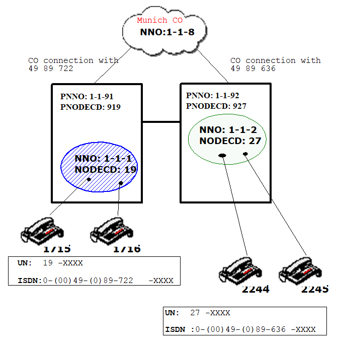
Figure 56. Before the move (non-overlapping virtual nodes)
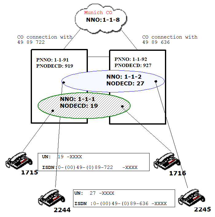
What is new about this example is the feature of overlapping node.
In Figure Figure 58,
the initial state is shown. The normal configuration still exists with
a 1:1 assignment from the physical to the virtual node.
In the next Figure 58,
Subscriber 1716, which was originally configured in the system with PNNO
1-1-91, moved within the system with PNNO 1-1-92. The subscriber wanted
to keep his or her fully qualified number (not just the extension). The
same applies for Subscriber 2244, who was originally configured in 1-1-92
and then moved to 1-1-91.
Figure 57. Overlapping Nodes
Abbreviations: UN = UNKNOWN, xxxx = station number (1 - 6 digits,
8 digits in special configurations). Prefixes are specified in parentheses.
In this example, the ISDN numbers are also three-level according to
the rule following the three-level node numbers. In the OpenScape 4000
specific numbering plan with tie line codes, however, where the numbers
should be as short as possible, numbering usually continues to be one-level
(e.g. one-level node code).
In this example, physical nodes 1-1-91 and 1-1-92 form an overlapping
area since there are overlapping virtual nodes between them. If the extensions
in the overlapping area are unambiguous, a simplified configuration can
be used that have performance advantages in comparison with the configuration
shown in the next chapter. Such a (sub)net could also be closed-numbered
and the configuration also works with a mixed format of closed and open
numbering.
Configuration in physical node 1-1-91 before the move
Before the move, the following configuration was present:
Set the node table:
ADD-KNDEF:NNO=1-1-1,TYPE=OWN,ISDNCC=49,ISDNAC=89,
ISDNLC=722,ISDNSK=3,ISDNUL=EXT,NODECD=19,NODECDSK=2;

CHANGE-KNDEF:NNO=1-1-1,DFLT=Y;
All subsequently configured subscribers are assigned this
virtual node by default (due to DFLT=Y). Here, however, is the command
by means of which you can explicitly assign a subscriber a virtual NNO.
Subscribers 1715 and 1716, however, are both still in the same virtual
nodes:
CHANGE-SDAT:STNO=1715,TYPE=DATA1,NNO=1-1-1;

CHANGE-SDAT:STNO=1716,TYPE=DATA1,NNO=1-1-1;
Both subscribers are normally set up and configured in
WABE.
Set the node prefix table for NPI=ISDN:
ADD-KNPRE:NPI=ISDN,TON=INTERNAT,EXIT=0,PREFIX=00;

ADD-KNPRE:NPI=ISDN,TON=NATIONAL,EXIT=0,PREFIX=0;

ADD-KNPRE:NPI=ISDN,TON=SUBSCR,EXIT=0;
Enter the own physical node number and code in the ZAND
data:
CHANGE-ZAND:TYPE=ALLDATA,PNNO=1-1-91,PNODECD=919;
Set the own codes in WABE:
ADD-WABE:CD=919,DAR=OWNNODE;/*PNODECD*/

ADD-WABE:CD=19,DAR=OWNNODE;/*NODECD*/
Set CO exit codes in WABE:
ADD-WABE:CD=0,DAR=TIE;
Set tie line codes for UNKNOWN in WABE:
ADD-WABE:CD=27,DAR=TIE;
You can set up the trunk groups for direct CO connection,
the trunk circuit, and the tie trunk as show in the previous examples.
You must set the node connection matrix only for the UNKNOWN numbering
plan according to the rules in Section .
CHA-KNMAT:NPI=UNKNOWN,LEVEL=0,ONNOL=OWN,
DNNOL=ROW,NUMEXT=#####;

CHA-KNMAT:NPI=UNKNOWN,LEVEL=0,ONNOL=ROW,
DNNOL=OWN,NUMRED=#####;
The following setting results:
---------------------------------------------------------------------------
NODE MATRIX FOR NPI = UNKNOWN, LEVEL = 0, OWN NNO = 1-1-100
---------------------------------------------------------------------------
ONNO   |DNNO   |CONN|MODCON| NUMEXT                   | NUMRED
/ ONNOL|/ DNNOL|    |      |                          |
-------+-------+----+------+--------------------------+------------------------
  1    |ROW    | A  |ALL   | 19                       | -
------+------+----+------+------------------------+------------------------
ROW   | 1    | A    |ALL   | -                        | 19
Set the node format table for CO node 1-1-8, which expects the calling number in international
format and the screening indicator NETWPROV (network provided, i.e. the number is
checked by the
network):
ADD-KNFOR:DNNO=1-1-8,NPI=ISDN,TONOUT=INTERNAT,
SCRE=NETWPROV;
Setting the CO route with LCR:
ADD-RICHT:MODE=LRTENEW,LRTE=20,LSVC=ALL,NAME="AMT_S2",
TGRP=71,DNNO=1-1-8;

ADD-LODR:ODR=20,CMD=ECHO,FIELD=3;

ADD-LODR:ODR=20,CMD=END;

ADD-LDAT:LROUTE=20,LSVC=ALL,LVAL=1,TGRP=71,ODR=20;

ADD-LDPLN:LDP=0-W-X,LROUTE=20,LAUTH=1;
Set the tie line routes, outdial rules, route elements, and dial pattern plan in LCR
for the
ISDN numbering plan. Here, only the AMOs and parameters important for this example
are
shown:
/* To remote Node 1-1-2 with three-level ISDN */

ADD-RICHT:MODE=LRTENEW,LRTE=203,...,DNNO=1-1-2;/* For dialing in
int. format */

ADD-RICHT:MODE=LRTENEW,LRTE=204,...,DNNO=1-1-2;/* For dialing in
nat. format */

ADD-RICHT:MODE=LRTENEW,LRTE=205,...,DNNO=1-1-2;/* For dialing in
sub. format*/
The outdial rule is to be formulated according to the desired format of the called
party. In
general, the international format is used in the ISDN numbering plan so that different
outdial
rules are required for the three dialing formats.
ADD-LODR:ODR=23,CMD=ECHO,FIELD=4;

ADD-LODR:ODR=23,CMD=ECHOALL;

ADD-LODR:ODR=23,NPI=ISDN,TON=INTERNAT;

ADD-LODR:ODR=23,CMD=END;

ADD-LODR:ODR=24,CMD=OUTPULSE,DGTS=49;

ADD-LODR:ODR=24,CMD=ECHO,FIELD=4;

ADD-LODR:ODR=24,CMD=ECHOALL;

ADD-LODR:ODR=24,NPI=ISDN,TON=INTERNAT;

ADD-LODR:ODR=24,CMD=END;

ADD-LODR:ODR=25,CMD=OUTPULSE,DGTS=4989;

ADD-LODR:ODR=25,CMD=ECHO,FIELD=3;

ADD-LODR:ODR=25,CMD=ECHOALL;

ADD-LODR:ODR=25,NPI=ISDN,TON=INTERNAT;

ADD-LODR:ODR=25,CMD=END;


 ADD-LDAT:LROUTE=203,.., ODR=23;

ADD-LDAT:LROUTE=204,.., ODR=24;

ADD-LDAT:LROUTE=205,.., ODR=25;


 ADD-LDPLN:LDP=0-W-00-4989636-X,LROUTE=203,LAUTH=1;
/* For dialing in international format*/

ADD-LDPLN:LDP=0-W-0-89636-X,LROUTE=204,LAUTH=1;
/* For dialing in nat. format*/

ADD-LDPLN:LDP=0-W-636-X,LROUTE=205,LAUTH=1;
/*For dialing in sub. format*/


/* To own node 1-1-1 with three-level ISDN */
Attention: As long as no subscriber has moved, these entries are optional! They make
it
possible for subscribers to reach other subscribers in their own node not just through
their own
extension, but also using an international, national, or subscriber number without
using the
public central office in the process.
ADD-RICHT:MODE=LRTENEW,LRTE=101,...,DNNO=1-1-1;
/* For dialing in ISDN format*/
With the RERTEINT attribute, you can mark a route element as a route element that
leads to the
own node from OpenScape 4000 and higher. No line is occupied (the trunk group specification
is
ignored), only the outdial rule is executed and the dial analysis is restarted. The
outdial rule
must be set up in such a way that only the extension is resent to the dial analysis.
ADD-LODR:ODR=26,CMD=ECHO,FIELD=5;

ADD-LODR:ODR=26,CMD=END;

ADD-LDAT:LROUTE=101,.., ODR=26,LATTR=RERTEINT;

ADD-LDPLN:LDP=0-W-00-4989722-X,LROUTE=101,LAUTH=1;

ADD-LDPLN:LDP=0-W-0-89722-X,LROUTE=101,LAUTH=1;

ADD-LDPLN:LDP=0-W-7-22-X,LROUTE=101,LAUTH=1;
Set the tie line routes, outdial rules, route elements, and dial pattern plan in LCR
for the
UNKNOWN numbering plan:
/* To remote Node 1-1-2 with one-level UNKNOWN */

ADD-RICHT:MODE=LRTENEW,LRTE=206,LSVC=ALL,NAME="UNKNOWN 1-1-2",
TGRP=74,DNNO=1-1-2;

ADD-LODR:ODR=22,CMD=ECHO,FIELD=1;

ADD-LODR:ODR=22,CMD=ECHO,FIELD=2;

ADD-LODR:ODR=22,CMD=END;

ADD-LDAT:LROUTE=206,LSVC=ALL,LVAL=1,TGRP=74,ODR=22;

ADD-LDPLN:LDP=27-X,LROUTE=206,LAUTH=1;
Configuration in physical node 1-1-92 before the move
Set the node table:
ADD-KNDEF:NNO=1-1-2,TYPE=OWN,ISDNCC=49,ISDNAC=89,ISDNLC=636,
ISDNSK=3,ISDNUL=EXT,NODECD=27,NODECDSK=2;

CHANGE-KNDEF:NNO=1-1-2,DFLT=Y;
All subsequently configured subscribers are assigned this
virtual node by default (due to DFLT=Y). Here, however, is the command
by means of which you can explicitly assign a subscriber a virtual NNO.
Subscribers 2244 and 2245, however, are both still in the same virtual
nodes:
CHANGE-SDAT:STNO=2244,TYPE=DATA1,NNO=1-1-2;

CHANGE-SDAT:STNO=2245,TYPE=DATA1,NNO=1-1-2;
Set the node prefix table:
ADD-KNPRE:NPI=ISDN,TON=INTERNAT,EXIT=0,PREFIX=00;

ADD-KNPRE:NPI=ISDN,TON=NATIONAL,EXIT=0,PREFIX=0;

ADD-KNPRE:NPI=ISDN,TON=SUBSCR,EXIT=0;
Enter the own physical node number and code in the ZAND
data:
AE-ZAND:TYPE=ALLDATA,PNNO=1-1-92,PNODECD=927;
Set the own codes in WABE:
ADD-WABE:CD=927,DAR=OWNNODE;/*PNODECD*/

ADD-WABE:CD=27,DAR=OWNNODE; /*NODECD*/
Set CO exit codes in WABE:
ADD-WABE:CD=0,DAR=TIE;
Set tie line codes for UNKNOWN in WABE:
ADD-WABE:CD=19,DAR=TIE;
You can set up the trunk groups for direct CO connection,
the trunk circuit, and the tie trunk as show in the previous examples.
You must set the node connection matrix only for the UNKNOWN numbering
plan according to the rules in Section 41.2.1.5,
"Source/destination-dependent number modification in the ISDN or
PNP numbering plan".
CHA-KNMAT:NPI=UNKNOWN,LEVEL=0,ONNOL=OWN,DNNOL=ROW,
NUMEXT=#####;

CHA-KNMAT:NPI=UNKNOWN,LEVEL=0,ONNOL=ROW,DNNOL=OWN,
NUMRED=#####;
The following setting results:
---------------------------------------------------------------------------
NODE MATRIX FOR NPI = UNKNOWN, LEVEL = 0, OWN NNO = 1-1-100
---------------------------------------------------------------------------
ONNO   |DNNO   |CONN|MODCON| NUMEXT                   | NUMRED
/ ONNOL|/ DNNOL|    |      |                          |
-------+-------+----+------+--------------------------+------------------------
  1    |ROW    | A  |ALL   | 27                       | -
-------+-------+----+------+--------------------------+------------------------
ROW    | 1     | A  |ALL   | -                        | 27
Set the node format table for CO node 1-1-8, which expects the calling number in international
format and the screening indicator NETWPROV (network provided, d.h. the number is
checked by the
network):
ADD-KNFOR:DNNO=1-1-8,NPI=ISDN,TONOUT=INTERNAT,
SCRE=NETWPROV;
Setting the CO route with LCR:
ADD-RICHT:MODE=LRTENEW,LRTE=20,LSVC=ALL,NAME="AMT_S2",
TGRP=71,DNNO=1-1-8;

ADD-LDPLN:LDP=0-W-X,LROUTE=20,LAUTH=1;
Set the tie line routes, outdial rules, route elements, and dial pattern plan in LCR
for the
ISDN numbering plan. Here, only the AMOs and parameters important for this example
are
shown:
/* To remote Node 1-1-1 with three-level ISDN */

ADD-RICHT:MODE=LRTENEW,LRTE=103,...,DNNO=1-1-1;
/*für Wahl im int. Format*/

ADD-RICHT:MODE=LRTENEW,LRTE=104,...,DNNO=1-1-1;
/* For dialing in nat. format*/

ADD-RICHT:MODE=LRTENEW,LRTE=105,...,DNNO=1-1-1;
/*For dialing in sub. format*/

ADD-LODR:ODR=23,CMD=ECHO,FIELD=4;

ADD-LODR:ODR=23,CMD=ECHOALL;

ADD-LODR:ODR=23,NPI=ISDN,TON=INTERNAT;

ADD-LODR:ODR=23,CMD=END;

ADD-LODR:ODR=24,CMD=OUTPULSE,DGTS=49;

ADD-LODR:ODR=24,CMD=ECHO,FIELD=4;

ADD-LODR:ODR=24,CMD=ECHOALL;

ADD-LODR:ODR=24,NPI=ISDN,TON=INTERNAT;

ADD-LODR:ODR=24,CMD=END;

ADD-LODR:ODR=25,CMD=OUTPULSE,DGTS=4989;

ADD-LODR:ODR=25,CMD=ECHO,FIELD=3;

ADD-LODR:ODR=25,CMD=ECHOALL;

ADD-LODR:ODR=25,NPI=ISDN,TON=INTERNAT;

ADD-LODR:ODR=25,CMD=END;

ADD-LDAT:LROUTE=103,.., ODR=23;

ADD-LDAT:LROUTE=104,.., ODR=24;

ADD-LDAT:LROUTE=105,.., ODR=25;

ADD-LDPLN:LDP=0-W-00-4989722-X,LROUTE=103,LAUTH=1;
/* For dialing in int. format*/

ADD-LDPLN:LDP=0-W-0-89722-X,LROUTE=104,LAUTH=1;
/* For dialing in nat. format*/

ADD-LDPLN:LDP=0-W-722-X,LROUTE=105,LAUTH=1;
/*For dialing in sub. format*/

/* To own Node 1-1-2 with three-level ISDN */
Attention: As long as no subscriber has moved, these entries are optional!
You thus make it possible for subscribers to reach other subscribers in their own
node not
just through their own extension, but also using an international, national, or subscriber
number without using the public central office in the process.
ADD-RICHT:MODE=LRTENEW,LRTE=201,...NAME="REROUTE 1-1-1",
DNNO=1-1-2;
With the RERTEINT attribute, you can mark a route element as a route element that
leads to the
own node from OpenScape 4000 and higher. No line is occupied (the trunk group specification
is
ignored), only the outdial rule is executed and the dial analysis is restarted:
ADD-LODR:ODR=26,CMD=ECHO,FIELD=5;

ADD-LODR:ODR=26,CMD=END;

ADD-LDAT:LROUTE=201,.., ODR=26,LATTR=RERTEINT;

ADD-LDPLN:LDP=0-W-00-4989636-X,LROUTE=201,LAUTH=1;

ADD-LDPLN:LDP=0-W-0-89636-X,LROUTE=201,LAUTH=1;

ADD-LDPLN:LDP=0-W-6-36-X,LROUTE=201,LAUTH=1;
Set the tie line routes, outdial rules, route elements, and dial pattern plan in LCR
for the
UNKNOWN numbering plan:
/* To remote Node 1-1-1 with one-level UNKNOWN */
ADD-RICHT:MODE=LRTENEW,LRTE=106,LSVC=ALL,NAME=UNKNOWN,
TGRP=74,DNNO=1-1-1,PDNNO=1-1-92;

ADD-LODR:ODR=22,CMD=ECHO,FIELD=1;

ADD-LODR:ODR=22,CMD=ECHO,FIELD=2;

ADD-LODR:ODR=22,CMD=END;

ADD-LDAT:LROUTE=106,LSVC=ALL,LVAL=1,TGRP=74,ODR=22;

ADD-LDPLN:LDP=19-X,LROUTE=106,LAUTH=1;
Changes in the Configuration after the Move
For the move from 1716 to physical node 1-1-92, you must make the
following changes:
- In physical node 1-1-91:
The WABE entry for 1716 as a subscriber in the own system must be changed on the external system after the subscriber configuration was deleted. The setup takes place using destination numbers as in the case of closed numbering.Routes that have a destination node number of 1-1-1 must be redefined, whereby the newly arising node portion on physical node 1-1-92 is meant. These routes must be assigned to route elements that occupy the tie line route.
- If you would like to give internal subscribers the choice of ISDN numbers in
international, national, or subscriber format, the existing dial plan must be expanded
for
the own ISDN codes. Subscriber 1716 should be removed from the reroute internal configuration
and a subscriber-specific entry that leads to the partner node should be made for
1716.
Without this entry, a reroute internal run with renewed dial analysis would also lead
to this
result, but this loop can be prevented and thus a higher performance can be
achieved.
ADD-RICHT:MODE=LRTENEW,LRTE=103,...,DNNO=1-1-1;PDNNO=1-1-92;

ADD-LDAT:LROUTE=103,LSVC=ALL,LVAL=1,TGRP=74,ODR=26;

ADD-LDPLN:LDP=0-W-00-4989722-1716,LROUTE=103,LAUTH=1;

ADD-LDPLN:LDP=0-W-0-89722-1716,LROUTE=103,LAUTH=1;

ADD-LDPLN:LDP=0-W-722-1716,LROUTE=103,LAUTH=1;
The specification of the fields of the dial pattern is oriented on the requirements of the outdial rule and thus on the desired format of the called party. In the following, a closed numbering is set up in the physical node 1-1-91 for the stations that moved (all subscribers within the virtual node 1-1-1 can thus reach each other by dialing the number).ADD-RICHT:MODE=CD,LRTE=207,CD=0101,SVC=ALL, NAME="NODE 1-1-1", DESTNO=1,DNNO=1-1-1,PDNNO=1-1-92; ADD-LODR:ODR=10,CMD=ECHO,FIELD=1; ADD-LODR:ODR=10,CMD=END; ADD-LDAT:LROUTE=207,LSVC=ALL,LVAL=1,TGRP=74,ODR=10; CHANGE-WABE:CD=1716,DESTNO=1;
- If you would like to give internal subscribers the choice of ISDN numbers in
international, national, or subscriber format, the existing dial plan must be expanded
for
the own ISDN codes. Subscriber 1716 should be removed from the reroute internal configuration
and a subscriber-specific entry that leads to the partner node should be made for
1716.
Without this entry, a reroute internal run with renewed dial analysis would also lead
to this
result, but this loop can be prevented and thus a higher performance can be
achieved.
- In physical node 1-1-92:
- The virtual node 1-1-1 extends to this physical node and must be made known. The same
configuration of NNO 1-1-1 as in physical node 1-1-91 is to be used. This node is
added to
1-1-2, but remains
1-1-2.
ADD-KNDEF:NNO=1-1-1,TYPE=OWN, ISDNCC=49,ISDNAC=89,ISDNLC=722,
ISDNSK=3,ISDNUL=EXT, NODECD=19,NODECDSK=2;
- Subscriber 1716 must be set up with a subscriber AMO as usual, but the node to which
he or
she belongs must then be changed so that the modification can be properly performed
for this
subscriber:
CHANGE-SDAT:STNO=1716,TYPE=DATA1,NNO=1-1-1;
- If Subscriber 1716 should also be reached with his or her ISDN number in international,
national, or subscriber format without a CO connection being established, reroute
internal
should be
used:
ADD-LDAT:LROUTE=101,.., ODR=26,LATTR=RERTEINT;
/* already set up */

ADD-LDPLN:LDP=0-W-00-4989722-1716,LROUTE=101,LAUTH=1;

ADD-LDPLN:LDP=0-W-0-89722-1716,LROUTE=101,LAUTH=1;

ADD-LDPLN:LDP=0-W-7-22-1716,LROUTE=101,LAUTH=1;
- The same applies to the one-level OpenScape 4000 numbering
plan:
ADD-RICHT:MODE=LRTENEW,LRTE=102,LSVC=ALL,NAME="REROUTE 1-1-1",
TGRP=74, DNNO=1-1-1,PDNNO=1-1-92;

ADD-LODR:ODR=10,CMD=ECHO,FIELD=2;

ADD-LODR:ODR=10,CMD=END;

ADD-LDAT:LROUTE=102,LSVC=ALL,LVAL=1,TGRP=74,
ODR=10,LATTR=RERTEINT;

ADD-LDPLN:LDP=19-1716,LROUTE=102,LAUTH=1;
Adapting the outdial rule for the existing digit pattern 19-X:CHANGE-LDAT:LROUTE=106,LSVC=ALL,LRTEL=1,ODR=10;
- The virtual node 1-1-1 extends to this physical node and must be made known. The same
configuration of NNO 1-1-1 as in physical node 1-1-91 is to be used. This node is
added to
1-1-2, but remains
1-1-2.
You can configure the move of Subscriber 2244 to the other system analogously.
You must now set the node connection matrix for the UNKNOWN numbering
plan again according to the rules in Section 41.2.1.5,
"Source/destination-dependent number modification in the ISDN or
PNP numbering plan" as follows:
CHA-KNMAT:NPI=UNKNOWN,LEVEL=0,ONNOL=OWN,DNNOL=ROW,
NUMEXT=#####;

CHA-KNMAT:NPI=UNKNOWN,LEVEL=0,ONNOL=ROW,DNNOL=OWN,
NUMRED=#####;
IMPORTANT:
The moved subscriber now uses the
LCR and, usually, the CO route located in the new system. (For the carrier/central
office, it is possible to request the ""No Screening Options" feature
to specify the appropriate "calling party number" in the outgoing direction
as well.)